Export from QGis to CAD » History » Version 31
« Previous -
Version 31/35
(diff) -
Next » -
Current version
Giulio Di Anastasio, 06/05/2021 17:31
Export from QGis to CAD
An algorithm has been created by Selvarani, to see the whole process click here:
https://redmine.auroville.org.in/projects/gis/wiki/Automatic_export_from_QGis_to_dxf
QGis Graphical Modeler: An algorithm to automatically export data directly from Gisaf to .dxf format (CAD)
- Login to PostGIS
- Directly from the Gisaf server, load all the layers which need to be converted into .dxf format
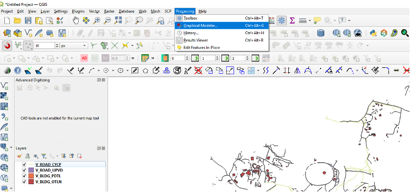
- Go to Processing Menu, click on “Graphical Modeler” (or Ctrl+Alt+G)
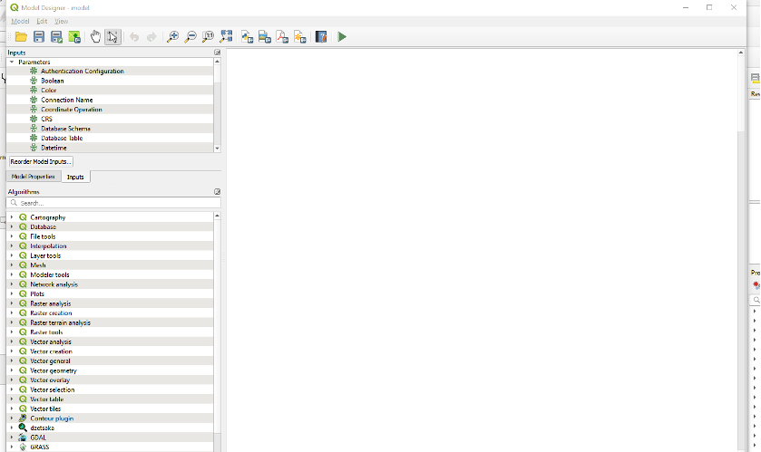
- The “Model Designer” window will open:
The final model will look like this:
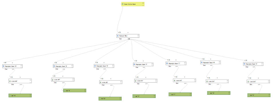
Below, the explanation on how the algorithm has been created.
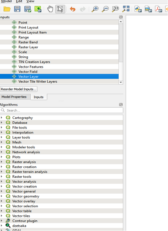
- An input to the algorithm is needed: go to “Inputs” tab and double click on “Vector Layer”
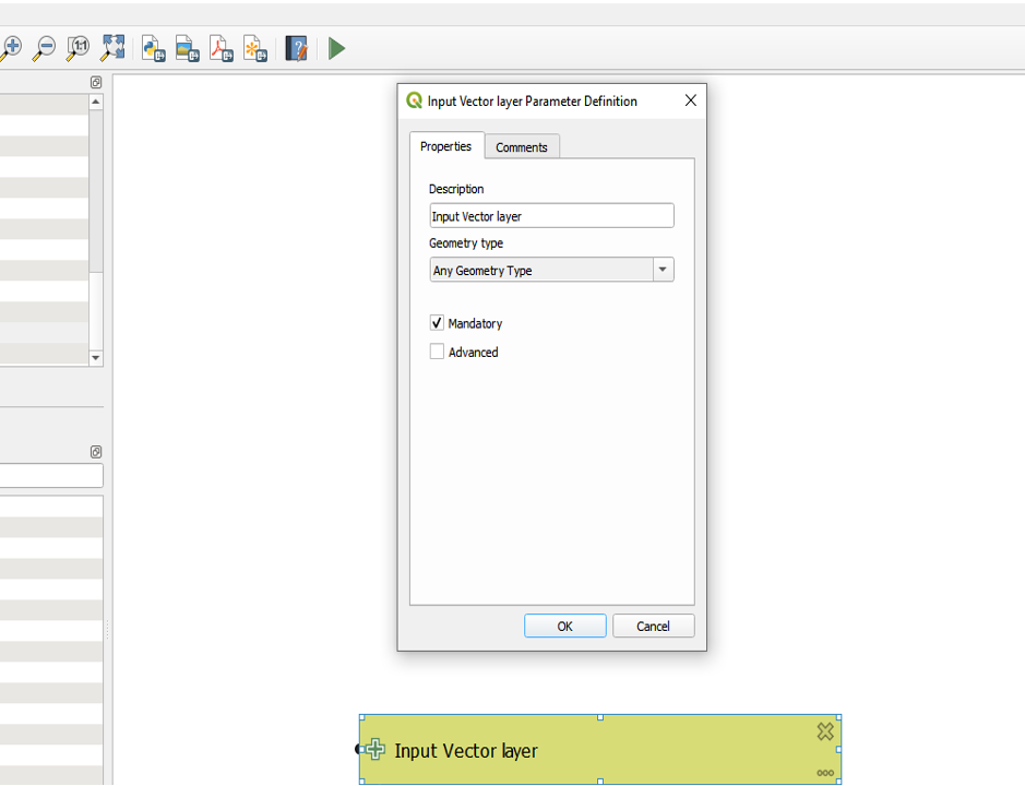
The window “Input Vector layer Parameter Definition” will open:
- in “Description”, enter “Input Vector layer”
- in “Geometry type” select “Any Geometry Type”
- Click “Ok”
Input is created as above.
As a second step, features need to be filtered, because some layers have different “Status” (E, D, F, etc. as defined in CSR Geomatics CAD Layer Naming Standards):
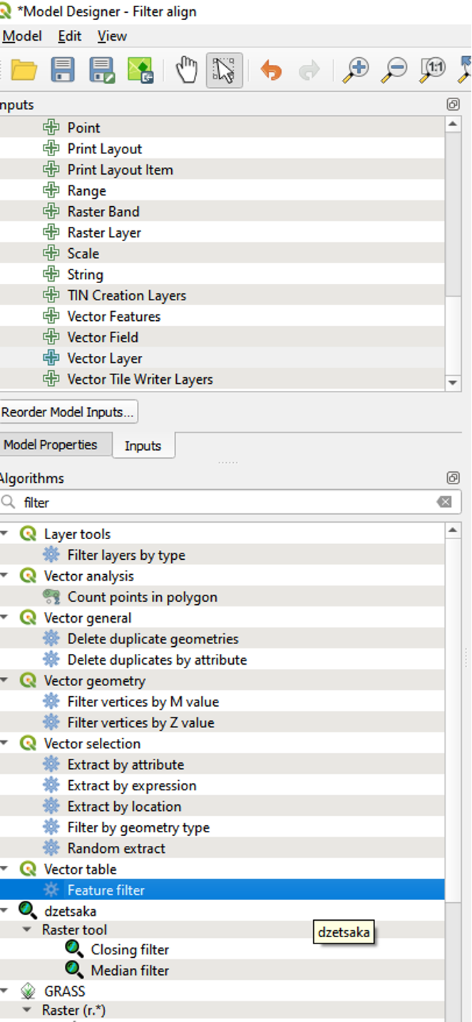
- in the Algorithms panel, type “filter” in the Search Box: this way, all existing algorithms related to “filter” will be listed
- double click on “Feature filter”
“Feature filter” window will open:
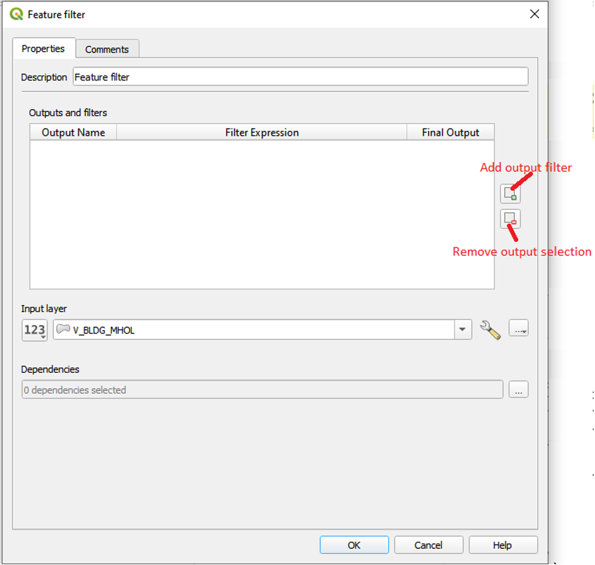
- Click on ‘Add output filter’ icon
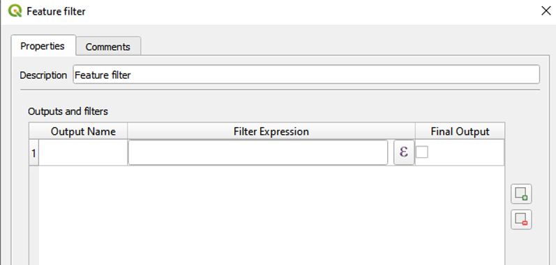
- Click on expression button
to write an expression for the filter.
- The Expression dialog will open, type the criteria for defining the filter, e.g. “STATUS”=’E’

- Click “Ok”: the expression is added in the table of “Outputs and filters” as below.
- In the field “Output Name”, type in the output as ‘E’.

- Repeat the same steps for all other status (Like D,F,N,T,M and X)
- Click on the “Input layer” button and select “Model Input” in the drop-down list, it will change to “Input Vector layer”. Click on “Ok”
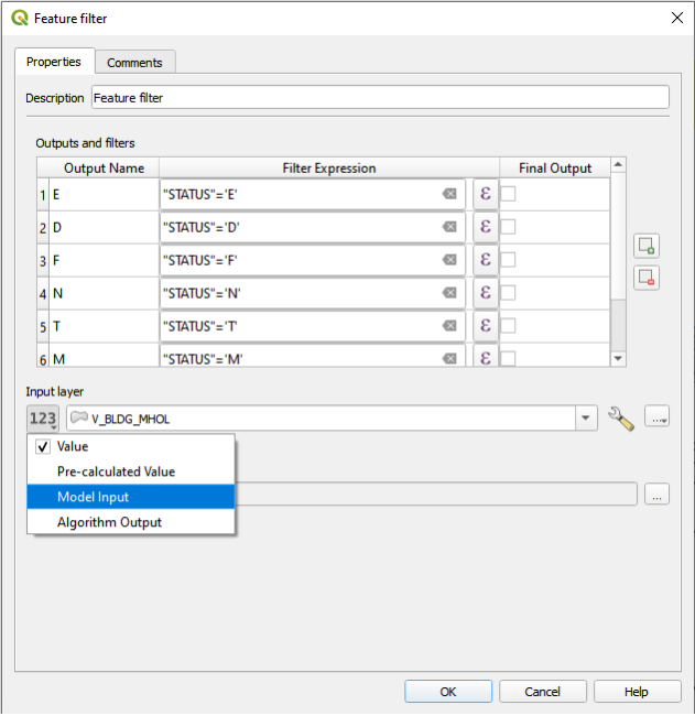

The model will look like below:

As the input layers were taken directly from Gisaf server, where their CRS is WGS 84-EPSG:4326, all outputs need to be reprojected in TM AUSPOS CRS, because the CAD overall survey map is in TM AUSPOS:
- Go to “Algorithms” panel and type “reproject” in the Search Box: this way, all existing algorithms related to “reproject” will be listed
- Double click on “Reproject layer” under “Vector general”
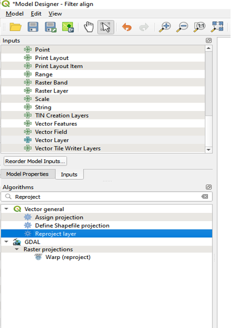
The “Reproject layer” dialog will open:
- In the “Description” box type “Reproject layer ‘E’”: this will reproject only the features with status ‘E’
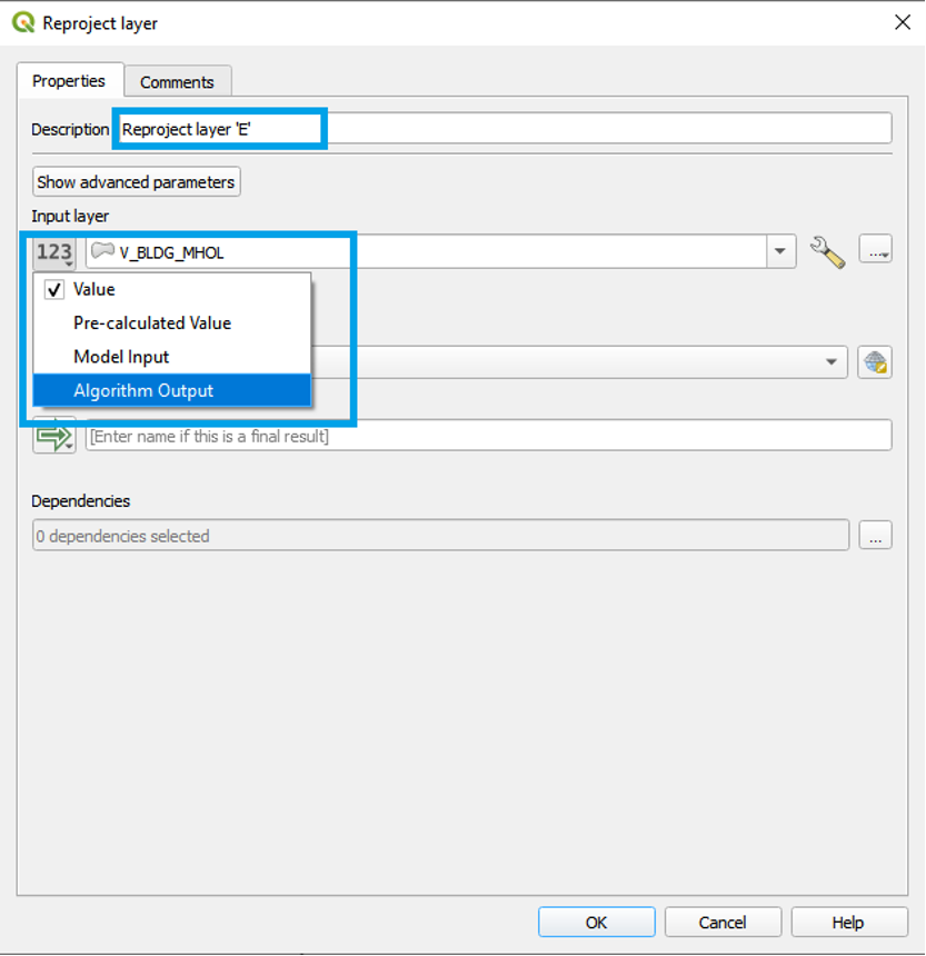
- In “Input layer” drop-down select “Algorithm Output”, click on the related box and a list of all available algorithm outputs will appear.
- In “Using algorithm output” select ““E” from algorithm “Feature filter””
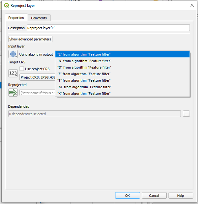
- In “Target CRS” select “USER;100028-TM AUSPOS”

- Click “Ok”. The model will look like below:
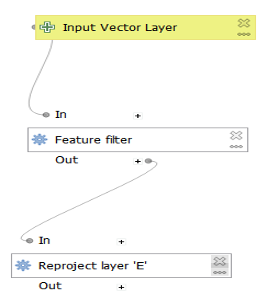
- Follow the same steps for all the status (N, D, F, T, M, X), from “Reproject” onwards
Once finished, the model will look like this:

The final step of the algorithm is to convert the outputs to .dxf format:
- Go to “Algorithms” panel, type “dxf” in the Search Box: this way, all existing algorithms related to “dxf” will be listed,
- Double click on “v.out.dxf” from “GRASS”

- The “v.out.dxf” window will open. In “Description” type “v.out.dxf ‘E’”
- In “Name of input vector map”, click on the button and select “Algorithm output”
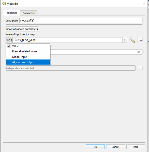
- In the drop-down list, select ““Reprojected” from algorithm “Reproject layer “E””

- In “DXF vector” type “DXF ‘E’”. This means that the dxf is the final output of the algorithm
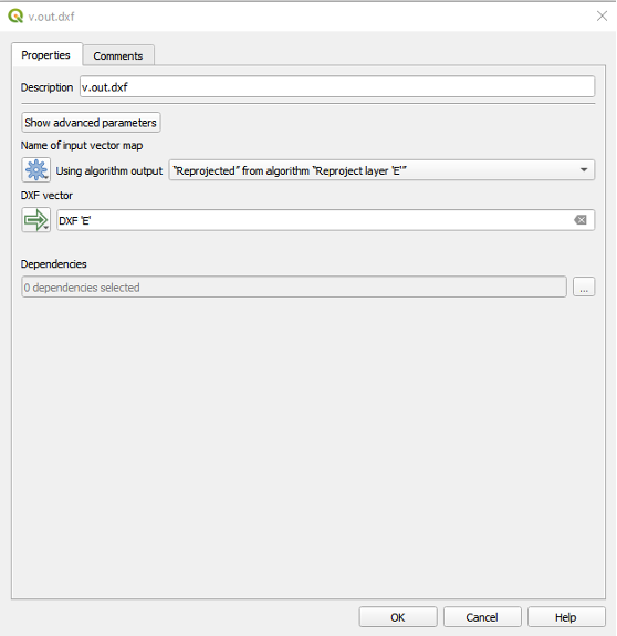
- Click “Ok”. Now the model will be as below:
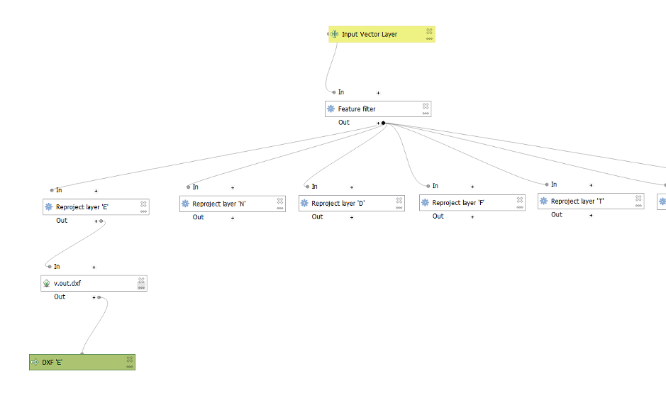
- Repeat the same steps for all other status.

The algorithm is now ready to convert QGis layers to .dxf format.
- To save the model, click on
“Save”
- “Save Model” window will open, give a name to the model (e.g. ‘Export SHP to DXF’) and save it.
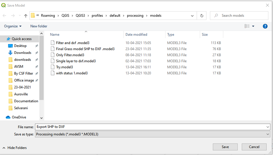
Once saved in the QGis models folder, the model can be opened from the Graphical Modeler and used directly:
- Click on
“Run model” icon.
The “Model” Dialog box will open:
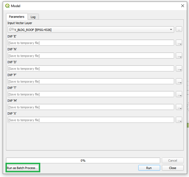
- Click on “Run as Batch Process”(bottom left corner),
- Batch Processing window will open
- Click on “Autofill” under ‘Input Vector layer’
- In the drop-down window, click on “Select from Open Layers”,
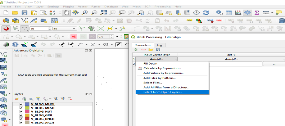
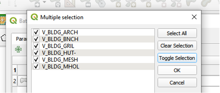
- The ‘Multiple selection’ box will open, click on “Select all”, then click on “Ok”.
